|
Home
>
Main Forum
>
Topic You have the wrong pin on the DME |  |
|
Buying through this link, gets PB a donation. |
Products for your Boxster, Cayman and Carrera. |
 | |
| 99 boxter with permanent cam sensor shorted faults _adrian_ - 9 years ago |
I have a 99 boxter 2.5 auto. Im getting the following codes permanently stored in the ecu. By permanent I mean will return asap as soon as engine is turned on.
p0341 cam sensor bank 1 short to b+
p1397 cam sensor bank 2 short to ground
Both sensors are new in the car and as soon as the car starts and runs the car will store both fault codes. The ecu has good powers and grounds. The reference voltage and ground to sensor is ok. Wiring to the sensors check out ok as well. The strange thing is I cant seem to locate any info on the signal wire pin 21 (88 pin ecu). Currently I have 12 volts at all times. Running or not. Not sure if that is ok. My impression is that the signal wire should not have this voltage. The voltage is actually coming out of the ecu. We removed the pin from the harness and the voltage is not present. Checked the pin out of the ecu and its putting out 12v. We actually went as far as pulling all of the connectors from the engine to see if there may be any feed back causing this issue same result pin 21 12v.
Cam timing is checked and the factory tools lock in place. Timing is up to spec. The thing that is strange is that I have no power with the a/c on during the idle to rev transition. Its almost as if the cam timing is advancing and we are getting overlap. With the variocam sensors un plugged and engine running same result. The only time it sounds normal (no deep intake noise) is when we pull the tps and run the car. Seems to run more normal in the idle to rev transition. Tps sensor tests ok. Maf plugged or un plugged same thing. I'm At my witts end with this thing and cant seem to solve it. Any help is appreciated.

| P0341 - Camshaft position sensor 1 signal implausible, short to ground, short to positive... MarcW - 9 years ago |
Possible fault causes: no power supply, break in wiring, short circuit to positive, short circuit to ground, camshaft position sensor faulty.
P1397 - Camshaft position sensor 2 signal implausible, short to ground, short to positive...
While there is more -- specifically electrical tests -- I don't have the time right now to type it in. I have the reference in my briefcase and will resume this tonight.
P1397 - Camshaft position sensor 2 signal implausible, short to ground, short to positive...
While there is more -- specifically electrical tests -- I don't have the time right now to type it in. I have the reference in my briefcase and will resume this tonight.
| Here are the tests for P0341... MarcW - 9 years ago |
As an aside while the codes are different they appear to be the same error just for different banks. This suggests a common failure which puts it away from the sensors and at the ECM or DME or in the wiring between the ECM/DME and the sensors (or the solenoids which control the actuators).
Test 1 - Power supply to camshaft position (CMP) sensor.
- remove connection from CMP sensor.
- turn the ignition switch to the ON position.
- connect a digital voltmeter to pin (negative) and pin 3 (positive).
Measure approx. 5V.
Test 2 - power supply wiring for continuity.
- remove connection from CMP sensor.
- connect special Porsche pin-out-box 9616 to wiring harness.
- connect a digital ohmmeter to special Porsche pin-out-box 9616 pin 53 and CMP sensor pin 3.
Measure 0 to 5 ohms.
Test 3 - Signal wire from ECM to CMP sensors.
- connect special Porsche pin-out-box 91616 to wiring harness.
- remove connectors from CMP sensors.
- connect digital ohmmeter to Porsche pin-out-box 9616 pin 21 and ground.
Measure infinity.
Test 4 - Signal wire from ECM to CMP sensors for short circuit to positive.
- connect special Porsche pin-out-box 9616 to wiring harness.
- remove connectors from CMP sensors.
- connect a digital ohmmeter to Porsche pin-out-box 9616 pin 21 and ground.
- turn on ignition switch the ON position.
Measure 0 voltage.

Quote
snc22782
MarcW,
What software/scanner are you using to be able to read that live voltage data on your computer?
a CarChip Pro (or Fleet Pro) which can be set up to read (among other things) battery voltage. Well, the CarChip doesn't read battery voltage like it reads say RPMs or vehicle speed. What it does is the firmware makes an AD/C measurement of the voltage level and converts the analog battery voltage to a digital voltage value.
Test 1) 5v
Test 2) .3 ohms
Test 3) 5 mega ohms (key still in ignition .45v) 9k ohms key out of ignition
Test 4) 12 v key on .45v key off but still in ignition
If i removed the ecu from the circuit and just tested the harness
test 3) 3 ohms
test 4) 0v (ecu is putting out the voltage through pin 21) I can remove pin 21 and leave the ecu connected and have 0v as well.
Same results with a test ecu i have here.
Test 3 is possibly where the major issue is. Hope we can figure this out. Its a strange one.
For example, with Test 3 there was no mention of what the reading should be with the key removed from the ignition switch. The test and test reading only are applicable if the key was turned to the ON position, which I want to stress is not the same as the start or accessory position.
| If test 4 failed that's indicative of a short to positive, based on the info from my... MarcW - 9 years ago |
reference.
A short to positive can be in the connector -- a pin or pin socket has been bent over or somehow caused to come in contact with something it shouldn't be in contact with. Then of course there is the wiring from the connector all the way back to the DME.
I'll see if I can find any more on this in my other reference at the office.
Ok so since we thought it could be an issue in the harness we pulled the engine harness out and tested it. pulled back the covers and looked for broken wires or any damage. Found none.
Now i have a good contact that parts out these cars. I acquired a harness that i can connect in the vehicle "overlay" not fully plugged in. Just the basic power, ground, ecu, and junction connections. Guess what......Still have 12v at pin 21.
With the transmission out of the circuit the problem is still there. I guess im looking at the body side of the harness and the connectors that are feeding through to the ecu. I saw two similar issues on these cars posted online. Neither have been able to fix them. Any ideas ill get back to looking for answers.
| Re: My references are for newer cars with DME version 7.8. If 12V is not measured in test 4.... _adrian_ - 9 years ago |
Marc,
Yes the initial test was performed as instructed and i had 12v on pin 21. Both harness stock and used from another car have the same voltage in pin 21 even with all the sensors removed and just the powers and ground connected including the connection in the trunk. We opened up the stock harness and looked for shorts found none. The wire is not shorted but the power is coming out of the ECU to the harness. I was able to remove the pin from the ecu connector and test the ecu directly through the plug to get this result. This is why i initially thought it was an ecu. I have two test ecu's and both do same. At this point i have to check the connections in the trunk back to the ecu this is where i believe my problem is. What a strange car.
Yes the initial test was performed as instructed and i had 12v on pin 21. Both harness stock and used from another car have the same voltage in pin 21 even with all the sensors removed and just the powers and ground connected including the connection in the trunk. We opened up the stock harness and looked for shorts found none. The wire is not shorted but the power is coming out of the ECU to the harness. I was able to remove the pin from the ecu connector and test the ecu directly through the plug to get this result. This is why i initially thought it was an ecu. I have two test ecu's and both do same. At this point i have to check the connections in the trunk back to the ecu this is where i believe my problem is. What a strange car.
Ok so i made some headway. Seems like the car had a visit to the body shop as some time. The connectors in the trunk for the main wiring harness had debris in them. Also by the convertible top the main wiring harness had several broken wires. Does anyone have the connector location charts for the rear trunk so i can identify the connector number. I can un plug one of the larger slide plugs and the voltage drops out of my pin. I want to see if i can find more info on this connector and the systems that it powers. Will help out big time in resolving this issue.
Thanks
Adrian
Thanks
Adrian
Boxsterra - 3 years ago |
Pin 88 on the DME is for OBD-2, nothing to do with the cam sensor.
Here is the wiring for the two cam sensors:
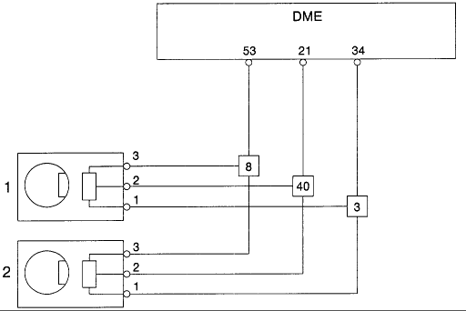
Pin 53 is power, common for most sensors
Pin 21 is the signal (incoming to the DME)
Pin 34 is ground, common tor most sensors
Edited 1 time(s). Last edit at 08/09/2020 10:47PM by Boxsterra. (view changes)
Here is the wiring for the two cam sensors:

Pin 53 is power, common for most sensors
Pin 21 is the signal (incoming to the DME)
Pin 34 is ground, common tor most sensors
Edited 1 time(s). Last edit at 08/09/2020 10:47PM by Boxsterra. (view changes)
Boxsterra - 3 years ago |

Sorry, only registered users may post in this forum.